After the great work you and the other software developers did to fix the city's flashing red traffic light problem, the mayor wants you to expand your skills to learn about the hardware side of the traffic light system as well.
I'm sure you've heard about the cross-training initiative being asked for by the mayor's office. All the folks on my hardware team have started an online course for Python and Visual Studio Code. While that's going on, I've got people from the traffic light manufacturer here to offer a hands-on seminar covering the basics of their hardware. We're inviting all the software developers to attend.
The traffic light system consists of red, yellow, and green LEDs attached to an ESP32C3 microcontroller. There are four connector pins on the traffic light. One for red, one for yellow, one for green, and a common ground pin. Each the LED pins is connected to a General Purpose Input-Output (GPIO) pin on the ESP32C3 microcontroller. In this activity, we'll look at how the GPIO hardware connections and software functions work together to let the microcontroller turn the traffic light LEDs on and off.

For review, the code that runs the traffic light system is shown below. It should look familiar from your previous work on fixing the flashing red light problem.
from machine import Pin
from time import sleep

red = Pin(4, Pin.OUT)
yellow = Pin(5, Pin.OUT)
green = Pin(6, Pin.OUT)

while True:
    red.on()
    yellow.off()
    green.off()
    sleep(5)

    red.off()
    yellow.off()
    green.on()
    sleep(4)

    red.off()
    yellow.on()
    green.off()
    sleep(1)
Last time you worked on the application, you spent your time looking
at the code in the while loop (the indented lines after
while True:) Everything above while True:
was ignored since it did not affect the timing of the lights.
This time around, we're going to look at the first few lines. This is the code that sets up the hardware.
Here are the relevant lines:
from machine import Pin

red = Pin(4, Pin.OUT)
yellow = Pin(5, Pin.OUT)
green = Pin(6, Pin.OUT)
The first line, from machine import Pin, tells
MicroPython to load the Pin class from the machine
module. A class is a predefined chunk of code you can use
in your applications. A module is a collection of those
predefined code chunks. You'll find lines like this in nearly
every MicroPython you see.
The Pin class is used three times: once for the red LED, again for the yellow, and finally for the green. Furthermore, each use of Pin gives a pin number (4, 5, or 6) and a direction (Pin.OUT). This is how the MicroPython software communicates with the ESP32C3 hardware.
Notice how the line with from time import sleep has
been omitted from this example. That's because it controls timing
of the light sequence and has no bearing on the hardware setup.
These four lines of MicroPython set up the the GPIO pins in the software. Now let's see what it looks like from the hardware side.
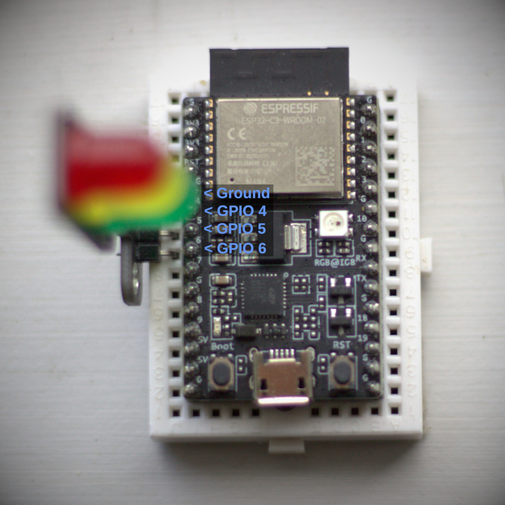
Below is a picture of the ESP32C3 microcontroller with labels added pointing to the pins used to control the traffic light LED. In this configuration, there are three GPIO pins and one ground reference attached to the LED module.

Notice how the pins are also labeled with white printing on the microcontroller board itself. The printed numbers are slightly offset to make use of the available space. The actual GPIO pin is the shiny silver metal bit beside it.
There is also a GPIO pin reference diagram you can use while working through this.
When you write MicroPython code that has a line like,
red = Pin(4, Pin.OUT), you're referring to a GPIO pin
on the microcontroller board. Pin 4 in this case. The LED module is
situated in so a pin connected to its red LED is plugged into the
same place as GPIO 4 on the microcontroller. This is why the
MicroPython code is written so red is equal to Pin 4.
Have a look at the traffic light code and see if you can figure out which GPIO pins on the microcontroller board connect to the yellow and green LEDs. Fill in your answers in the table below.
| GPIO Pin | LED Color |
|---|---|
| 4 | |
| 5 | |
| 6 |
| GPIO Pin | LED Color |
|---|---|
| 4 | |
| 5 | |
| 6 |
If you have access to a multimeter, use it to measure the voltage at the GPIO pins while the traffic light program is running.
| Traffic Signal Color | GPIO Pin 4 | GPIO Pin 5 | GPIO Pin 6 |
|---|---|---|---|
| Red | |||
| Yellow | |||
| Green |
| Traffic Signal Color | GPIO Pin 4 | GPIO Pin 5 | GPIO Pin 6 |
|---|---|---|---|
| Red | |||
| Yellow | |||
| Green |
The voltage should be 3.3 volts whenever the GPIO is in the on state and the LED is illuminated. GPIO voltage should be 0 volts when it's off. Measurements with the multimeter may not be exact, but they should be close, within 10% or so.
If you have a sharp eye, you may have noticed some of the other
pins labeled on the ESP32-C3 board. Specifically 3V3 and G. These
labels are for 3.3 volts and ground (or 0 volts). When you set a
GPIO to on using something like red.on() in your
program, it's changing the voltage on the GPIO 4 pin to 3.3 volts.
When you set it to off, with red.off(), the voltage
on the GPIO 4 pin becomes 0 volts.
This is how the program can make the LEDs light up. The software tells the microcontroller to turn the GPIO on. The microcontroller switches the GPIO pin voltage to 3.3 volts. This causes current to flow through the LED and the LED turns on.